Set up a drawing annotation
Before you start
|
Why would I use drawing annotation? Common uses include
|
|
Overview of process |
|
Step 1. Upload drawing
- Open the list entries of the list that will contain the drawing and click Add Item.
- If necessary create a list, giving a suitably meaningful name and ticking the boxes next to Associated image or document and Metres per pixel in the Additional Attributes for list entries tab.
- Enter Text that will enable the device user to identify the drawing in the list.
- In the Additional Attributes tab click Add Attachment and select the required drawing to upload. This can be a png, jpg, bmp or tiff but not a PDF.
- If the original is in PDF format, an internet tool might be useful for converting it.
- Make file sizes as small and the resolution as low as possible without making the drawing unclear and unusable. Graphic files can be extremely large so keep sizes to around 4000x2000 pixels and be aware that around 7000x3500 or more are likely to cause problems.
- Try to make filenames meaningful as this will help to make sure the correct one is attached.
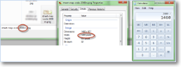
- Optionally, in the Additional Attributes tab, enter the Metres per pixel figure. This is obtained by taking the height or width of the drawing in pixels (as shown in the drawing's properties) and dividing it into the actual distance that it represents. This will provide a default distance for lines drawn using tools.
- Save.
- Repeat (if required) until all relevant drawings have been uploaded.
- When all the drawings have been uploaded into their respective lists, return to the list of Lists. Tick the boxes to the left of the list names and click on Mark as job specific.
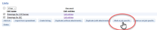
Image Title
Step 2. Link drawings to customer location
- Click on the required Location in the Customer screen (Setup/Maintenance -> Customers -> select customer name)
- In the Advanced tab select the list created in Step 1 (containing the drawings for this location) in the List of drawings/plans drop-down list.
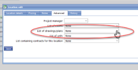
Image Title
- Save.
Step 3. Upload icons
- Open the list entries that will contain the icon to be available for annotating the drawings. If necessary create a list, giving a suitably meaningful name and ticking the box next to Associated image or document in the Additional Attributes for list entries tab.
- Enter text that will identify the icon for future amending (this will not appear on the device).
- In the Additional Attributes tab click Add Attachment and select the required icon to upload.
- Save.
- Repeat (if required) until all relevant icons have been uploaded.
Step 4. Customise colour pallette (optional)
- Open the list entries for the colour pallette. If necessary create a list, giving a suitably meaningful name and ticking the box next to Colour in the Additional Attributes for list entries tab.
- Enter text that will identify the colour on the device (eg green, alert, neutral, not inspected).
- In the Additional Attributes tab change the Colour shown if not as required.
- Save.
- Repeat (if required) until all required colours have been included in the palette.
Step 5. Create drop-down list for device user to select the drawing to use
-
Create a list called 'Drawing lists' (Create list). It doesn't need any attributes or list entries but acts as a placeholder in the drop-down list.
- it is useful to add one entry to this list along the lines of Drawings not configured for this customer or project as this will appear if there is nothing linked to the location.
- Open the template that will contain the drawing annotation by clicking on it in the template list (or create one - create a new template).
- Click Add Item in the required section and select Drop-down list.
- Main tab: enter a meaningful question for your device user (eg 'select floor plan') and select the list name from 1 above ('Drawing lists') under List name.
- Advanced tab: it is recommended to change the Unique name to something meaningful such as locationList, but this is not essential. Make a note of this unique name - it is needed in step 6.
- Also in the Advanced tab type drawingListId into the 'Attribute' name for location -specific list box. This is essential to link with the location selected when completing a form.
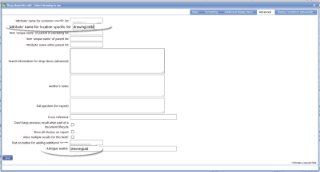
Image Title
Step 6. Create drawing annotation item on the device
- Use the template already used in Step 4.
- Click Add Item in the required section
- it is often best to add a whole new page, with a tab called Drawings and a section just for the drawing annotation.
- Select Drawing annotation (or Drawing location in some older versions).
- Main tab: the question is not essential, but may help to guide your device users. Mandatory, pen width, etc can be left as they are.
- Advanced tab: requires the unique name noted down in item 5 of Step 5 (eg locationList) to be entered in 'Unique name' of item containing the drawing to use. Everything else in this tab can be left as-is.
- Straight line, Spider and Chain tool tabs all have the same prompts. These do not need amending, but tick (or untick) the Enable [tool type] tool to allow (or disallow) the device user to select that tool type.
- Icon box tool is enabled by ticking the Enable icon placement. Select the list name from Step 3 under Icon list.
- Save.
- For more information on the above tabs, see Drawing annotation help page.
See Also